I needed to build something permanent
So for work, I needed to make the connection between a couple of RF components. I had a 4-way splitter and a 4-port RF switch and wanted to connect the two together for some testing. Each cable would carry the exact same signal, split from the splitter, to the switch, which would then select a port for passing the signal on towards the Device Under Test. The catch was that each cable should be a slightly different length, to phase shift the signal. Let’s just say that the amount of phase shift didn’t matter, it was covering a frequency band of 6-8GHz anyway, so the shift would depend on the frequency. That means that the actual cable lengths didn’t matter.


Design plan
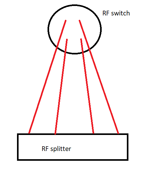
I thought it should be easy enough to connect the two devices together. My original concept was to do something like this image here.

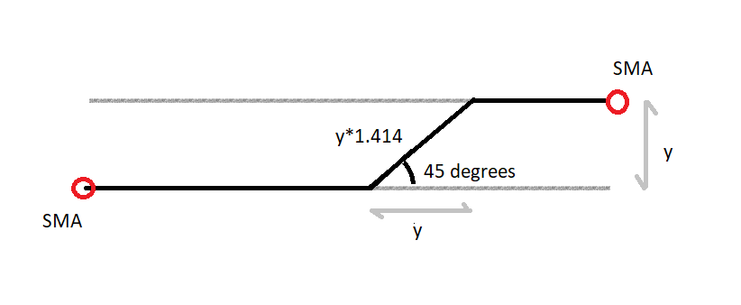
Then to connect the ports, I could do something similar to this.

Taking the datasheet for the RF switch, and for the RF splitter, we can get the actual sizes for these devices. The SMA spacing is the most important detail here, 12.7mm (P) for the splitter, and 13.5mm (F) / 23.4mm (J) for the switch. So if we take the image above, and look at length Y, and conceive this length as the spacing between each of the sma connectors. In order to achieve a single bend between the splitter and the switch, we can do a 45 degrees bend between two parallel connections. The length of the bend should be y*sqrt(2) (or y*1.414). This will account for the different length cables.
However, in order to take into account the position of sma connectors, I need to count more than one sma spacing.
I will replace y with the respective letters from the datasheets below.
| RF switch port | RF splitter port | cable length | actual cable length change |
|---|---|---|---|
| 1 | 4 | No change | 0 mm |
| 2 | 1 | P*sqrt(2) + J*sqrt(2) |
~5 mm |
| 3 | 2 | 2*P*sqrt(2) - F*sqrt(2) |
~15 mm |
| 4 | 3 | 3*P*sqrt(2) - F*sqrt(2) + J*sqrt(2) |
~21 mm |
Manufacturing
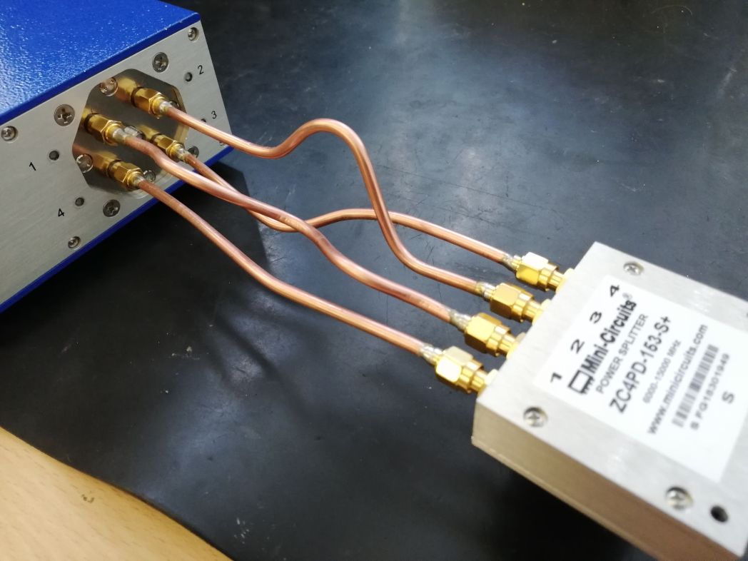
So, when I made those cables (This youtube video is a great tutorial for adding SMA connectors to those cables.), they measured up quite well to the table above. I tried to connect the cables. I quickly realised that the one bend idea was not going to work. The 5 mm cable just wasn’t going to fit in its position. It wouldn’t even fit in any position combination.
However, it would be remiss of me if I didn’t make them fit. There were a few extra bends required to make them fit, but it all worked out well in the end.

